Blinky-Lite Instrumentation
Interlock and digital-status monitoring
A wireless, three-channel, configurable interlock monitoring for reporting switch closures and digital safety states.
Overview
The Interlock Cube is a compact, wireless instrumentation module in the Blinky-Lite Instrumentation Platform. It is designed to report the status of interlocks and digital sensors near the equipment being monitored, then communicate states and alarms to a central Blinky-Lite control system.
Typical inputs include door switches, limit switches, motion detectors, bimetallic temperature switches, and other dry-contact or compatible digital status signals. Each of the three channels provides independently configurable source, input termination, and active-logic settings so the device can adapt to a wide range of field wiring and sensor arrangements.
Built around the Raspberry Pi Pico W / RP2040, the module uses 2.4 GHz Wi-Fi and MQTT publish/subscribe communication. This event-driven approach supports distributed deployments without wired data connections and enables Blinky-Lite to use device information for recording, notifications, visualisation, and machine-protection or interlock workflows.
| Enclosure | PCB |
|---|---|
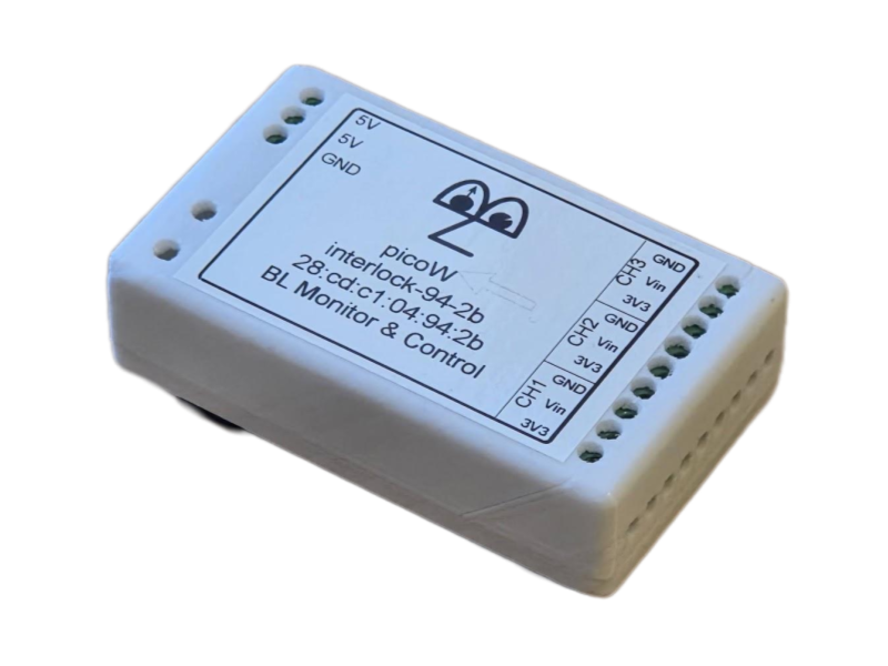 |
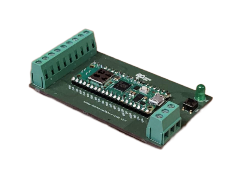 |
Key features
- Three configurable interlock channels: Monitor three independent switch closures or compatible digital sensor signals.
- Independently switched 3.3 V sources: Each channel has a 3.3 V source pin that can be remotely set on or off independently.
- Flexible input termination: Set each digital read pin remotely and independently to pull-up, pull-down, or floating.
- Configurable signal logic: Set active-high or active-low logic independently for each sensor input.
- PLC-style field wiring: 5 mm screw terminals simplify connection of sensors, interlock contacts, and power wiring in PLC-like installations.
- Event-driven integration: MQTT publish/subscribe communication with Blinky-Lite for prompt reporting of state changes.
- Wireless connectivity: 2.4 GHz Wi-Fi for remote or distributed installations.
- Open-source firmware: Microcontroller code can be adapted for site-specific instrumentation and integration requirements.
Typical applications
- Door and access interlocks
- Limit-switch and position-status monitoring
- Motion-detection status reporting
- Bimetallic temperature-switch monitoring
- Machine-protection and safety-workflow status inputs
Specifications
- Product Code
- interlock-cube
- Primary function
- Interlock and digital-status monitoring
- Sensor / interface
- Switch closures and compatible digital sensors, including door switches, limit switches, motion detectors, and bimetallic temperature switches
- Channels
- Three independently configurable interlock channels
- Channel source
- ne independently switched 3.3 V source pin per channel
- Digital read input
- One 3.3 V digital read pin per channel
- Input termination
- Remotely configurable pull-up, pull-down, or floating termination per channel
- Logic configuration
- Remotely configurable active-high or active-low logic per channel
- Inputs / outputs
- 5 mm screw terminals for field wiring, sensor connections, and 5 V power
- Power input
- 5 V DC via 5 mm screw terminals
- Wireless
- 2.4 GHz Wi-Fi
- Communication
- MQTT publish/subscribe protocol
- Controller
- Raspberry Pi Pico W / RP2040
- PCB dimensions
- 50 mm × 87 mm
- Enclosure and mounting
- 55 mm × 93 mm × 26 mm; DIN Mod3-compatible enclosure with removable DIN-rail mount
- Platform
- Blinky-Lite Instrumentation Platform
Getting started
Hardware
- Install the Interlock Cube close to the switches, sensors, or interlock circuits to be monitored.
- Connect each sensor or switch circuit to the assigned 5 mm screw terminals according to the product wiring documentation.
- Connect the regulated 5 V DC supply through the dedicated 5 mm screw terminals.
- Verify that the connected devices and wiring are compatible with the 3.3 V source and digital-read arrangements used for each channel.
- Mount the enclosure on a DIN rail when required, or remove the DIN-rail mount for an alternative installation.
Firmware build target
The firmware targets the Raspberry Pi Pico W / RP2040 using the Arduino-Pico board support.
- Board: Pico W / RP2040-compatible target
- Flash layout: Sketch 1920 KB, filesystem 128 KB
- FQBN flash option: flash=2097152_131072
Open-source software and licensing
The firmware is released under the MIT License, giving users broad permission to study, modify, and adapt the code for their own applications. The open hardware design can likewise be customised to suit site-specific requirements. The firmware uses the open-source Arduino-BlinkyPicoW library, which is also available under the MIT License.
Configuration
- Build and upload the firmware using the project’s source and configuration files.
- Use the onboard web interface to set or update Wi-Fi credentials.
- Configure the MQTT connection and create the corresponding device integration in Blinky-Lite.
- For each channel, set the 3.3 V source pin on or off as required by the connected field device.
- For each channel, set the digital-read termination to pull-up, pull-down, or floating.
- Set active-high or active-low logic independently for each sensor input.
- Verify that normal states, transitions, and alarm events appear as expected in Blinky-Lite.
Integration model
The Interlock Cube uses MQTT to publish sensor states and state-change events. This event-driven model avoids conventional polling and enables prompt control-system responses to changing interlock conditions.
In a typical deployment, the device connects by Wi-Fi to the network and communicates through an MQTT broker. Blinky-Lite represents it as an integrated instrumentation node and can use its information for recording, display, notification, alarms, and machine-protection logic.
Measurement, safety, and installation considerations
- Confirm that connected switches, sensors, circuits, and environmental conditions are within the product’s specified limits.
- Verify the required 3.3 V source setting, input termination, and active logic for every channel before operation.
- Validate normal operation and interlock-state behaviour before relying on the device for operational or protection decisions.
- Review field wiring, connector, cable, grounding, shielding, enclosure, and environmental requirements before installation.
- Assess the overall safety function and any required fault handling for the intended application; this module reports interlock status but does not replace a safety assessment of the complete system.